Networks
Networks are simply things connected. For example, your friendship circle: you are all connected because of similar interests, hobbies, skills and sorts.
Networks can be found in all walks of life:
- A city’s public transportation system
- Infrastructure such as the national power grid for electricity
- Meeting and greeting your neighbours
- Postal systems for sending letters and parcels
But more specifically, in computing, networking is the same idea, just dispersed to technological devices. Take your phone as an example; the reason that you have it is to access things. We’ll cover how these devices communicate with each other and the rules that follow.
In computing, a network can be formed by anywhere from 2 devices to billions. These devices include everything from your laptop and phone to security cameras, traffic lights and even farming!
Networks are integrated into our everyday life. Be it gathering data for the weather, delivering electricity to homes or even determining who has the right of way at a road. Because networks are so embedded in the modern-day, networking is an essential concept to grasp in cybersecurity.
Take the diagram below as an example, Alice, Bob and Jim have formed their network! We’ll come onto this a bit later on.

Internet
The Internet is one giant network that consists of many, many small networks within itself. Using our example from the previous task, let’s now imagine that Alice made some new friends named Zayn and Toby that she wants to introduce to Bob and Jim. The problem is that Alice is the only person who speaks the same language as Zayn and Toby. So Alice will have to be the messenger!

Because Alice can speak both languages, they can communicate to one another through Alice — forming a new network.
The first iteration of the Internet was within the ARPANET project in the late 1960s. This project was funded by the United States Defence Department and was the first documented network in action. However, it wasn’t until 1989 when the Internet as we know it was invented by Tim Berners-Lee by the creation of the World Wide Web (WWW). It wasn’t until this point that the Internet wasn’t used as a repository for storing and sharing information (like it is today).
Let’s relate Alice’s network of friends to computing devices. The Internet looks like a much larger version of this sort of diagram:

As previously stated, the Internet is made up of many small networks all joined together. These small networks are called private networks, where networks connecting these small networks are called public networks — or the Internet! So, to recap, a network can be one of two types:
- A private network
- A public network
To communicate and maintain order, devices must be both identifying and identifiable on a network. What use is it if you don’t know whom you’re talking to at the end of the day?
Devices on a network are very similar to humans in the fact that we have two ways of being identified:
- Our Name
- Our Fingerprints
Now we can change our name through deed poll, but we can’t, however, change our fingerprints. Every human has an individual set of fingerprints which means that even if they change their name, there is still an identity behind it. Devices have the same thing: two means of identification, with one being permeable. These are:
- An IP Address
- A Media Access Control (MAC) Address — think of this as being similar to a serial number.
IP Addresses
Every computer (host) that connects to a network needs to have a logical address. For instance, a host can be any system with network access, such as a laptop, a smartphone, and a Raspberry Pi. We refer to this address as logical because it’s assigned by software and could change over time, for example, when the host connects to a new network. The logical address, in this case, is the IP address.
IP stands for Internet Protocol. To keep things simple, we will consider Internet Protocol version 4 (IPv4). An IPv4 address is made up of 4 decimal numbers. The range for each number is from 0 to 255. Example IPv4 addresses are:
192.168.0.10172.16.0.10010.10.11.121.1.1.1
The first 3 IP addresses in the list above are private, meaning that they can only be accessed from the private network they belong to. The last IP address, 1.1.1.1, is a public IP address that can be accessed by the whole Internet and belongs to Cloudflare.
Some IP addresses serve a special purpose. For example, 127.0.0.1 is often referred to as the ‘loopback address’ or ‘localhost’. By default, any packet or traffic destined to this address won’t leave the host.
On Microsoft Windows, one way to find your IP address is by running ipconfig in the command prompt or PowerShell. On Linux and macOS, you can find your IP address by executing ip address show on the terminal. Note that ip will accept abbreviations of arguments such as ip addr show or even ip a s.
user@TryHackMe$ ip addr show
1: lo: mtu 65536 qdisc noqueue state UNKNOWN group default qlen 1000
    link/loopback 00:00:00:00:00:00 brd 00:00:00:00:00:00
    inet 127.0.0.1/8 scope host lo
       valid_lft forever preferred_lft forever
    inet6 ::1/128 scope host
       valid_lft forever preferred_lft forever
2: wlp1s0: mtu 1500 qdisc noqueue state UP group default qlen 1000
    link/ether 80:30:49:c8:28:b3 brd ff:ff:ff:ff:ff:ff
    inet 192.168.0.202/24 brd 192.168.0.255 scope global dynamic noprefixroute wlp1s0
       valid_lft 84435sec preferred_lft 84435sec
    inet6 fe80::c3:6a8f:ff22:cff/64 scope link noprefixroute
       valid_lft forever preferred_lft forever
The terminal output above shows that this Linux system has a wireless adaptor with the IP address 192.168.0.202.

An IP address is a set of numbers that are divided into four octets. The value of each octet will summarise to be the IP address of the device on the network. This number is calculated through a technique known as IP addressing & subnetting, but that is for another day. What’s important to understand here is that IP addresses can change from device to device but cannot be active simultaneously more than once within the same network.
IP Addresses follow a set of standards known as protocols. These protocols are the backbone of networking and force many devices to communicate in the same language, which is something that we’ll come onto another time. However, we should recall that devices can be on both a private and public network. Depending on where they are will determine what type of IP address they have: a public or private IP address.
A public address is used to identify the device on the Internet, whereas a private address is used to identify a device amongst other devices. Take the table & screenshot below as an example. Here we have two devices on a private network:
| Device Name | IP Address | IP Address Type |
|---|---|---|
| DESKTOP-KJE57FD | 192.168.1.77 | Private |
| DESKTOP-KJE57FD | 86.157.52.21 | Public |
| CMNatic-PC | 192.168.1.74 | Private |
| CMNatic-PC | 86.157.52.21 | Public |

These two devices will be able to use their private IP addresses to communicate with each other. However, any data sent to the Internet from either of these devices will be identified by the same public IP address. Public IP addresses are given by your Internet Service Provider (or ISP) at a monthly fee (your bill!)

As more and more devices become connected, it is becoming increasingly harder to get a public address that isn’t already in use. For example, Cisco, an industry giant in the world of networking, estimated that there would be approximately 50 billion devices connected on the Internet by the end of 2021. (Cisco., 2021). Enter IP address versions. So far, we have only discussed one version of the Internet Protocol addressing scheme known as IPv4, which uses a numbering system of 2^32 IP addresses (4.29 billion) — so you can see why there is such a shortage!
IPv6 is a new iteration of the Internet Protocol addressing scheme to help tackle this issue. Although it is seemingly more daunting, it boasts a few benefits:
- Supports up to 2^128 of IP addresses (340 trillion-plus), resolving the issues faced with IPv4
- More efficient due to new methodologies
The screenshot below compares both an IPv6 and IPv4 address.

MAC Addresses
Devices on a network will all have a physical network interface, which is a microchip board found on the device’s motherboard. This network interface is assigned a unique address at the factory it was built at, called a MAC (Media Access Control ) address. The MAC address is a twelve-character hexadecimal number (a base sixteen numbering system used in computing to represent numbers) split into two’s and separated by a colon. These colons are considered separators. For example, a4:c3:f0:85:ac:2d. The first six characters represent the company that made the network interface, and the last six is a unique number.

However, an interesting thing with MAC addresses is that they can be faked or “spoofed” in a process known as spoofing. This spoofing occurs when a networked device pretends to identify as another using its MAC address. When this occurs, it can often break poorly implemented security designs that assume that devices talking on a network are trustworthy. Take the following scenario: A firewall is configured to allow any communication going to and from the MAC address of the administrator. If a device were to pretend or “spoof” this MAC address, the firewall would now think that it is receiving communication from the administrator when it isn’t.
Places such as cafes, coffee shops, and hotels alike often use MAC address control when using their “Guest “or “Public” Wi-Fi. This configuration could offer better services, i.e. a faster connection for a price if you are willing to pay the fee per device.
Ping (ICMP)
Ping is one of the most fundamental network tools available to us. Ping uses ICMP (Internet Control Message Protocol) packets to determine the performance of a connection between devices, for example, if the connection exists or is reliable.
The time taken for ICMP packets travelling between devices is measured by ping, such as in the screenshot below. This measuring is done using ICMP’s echo packet and then ICMP’s echo reply from the target device.
Pings can be performed against devices on a network, such as your home network or resources like websites. This tool can be easily used and comes installed on Operating Systems (OSs) such as Linux and Windows. The syntax to do a simple ping is ping IP address or website URL. Let’s see this in action in the screenshot below.
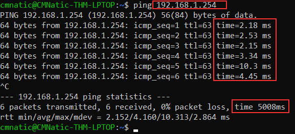
Here we are pinging a device that has the private address of 192.168.1.254. Ping informs us that we have sent six ICMP packets, all of which were received with an average time of 5.3 seconds.
LAN Topologies
Over the years, there has been experimentation and implementation of various network designs. In reference to networking, when we refer to the term “topology”, we are actually referring to the design or look of the network at hand. Let’s discuss the advantages and disadvantages of these topologies below.
Star Topology
The main premise of a star topology is that devices are individually connected via a central networking device such as a switch or hub. This topology is the most commonly found today because of its reliability and scalability - despite the cost.
Any information sent to a device in this topology is sent via the central device to which it connects. Let’s explore some of these advantages and disadvantages of this topology below:
Because more cabling & the purchase of dedicated networking equipment is required for this topology, it is more expensive than any of the other topologies. However, despite the added cost, this does provide some significant advantages. For example, this topology is much more scalable in nature, which means that it is very easy to add more devices as the demand for the network increases.
Unfortunately, the more the network scales, the more maintenance is required to keep the network functional. This increased dependence on maintenance can also make troubleshooting faults much harder. Furthermore, the star topology is still prone to failure - albeit reduced. For example, if the centralised hardware that connects devices fails, these devices will no longer be able to send or receive data. Thankfully, these centralised hardware devices are often robust.

Bus Topology
This type of connection relies upon a single connection which is known as a backbone cable. This type of topology is similar to the leaf off of a tree in the sense that devices (leaves) stem from where the branches are on this cable.
Because all data destined for each device travels along the same cable, it is very quickly prone to becoming slow and bottlenecked if devices within the topology are simultaneously requesting data. This bottleneck also results in very difficult troubleshooting because it quickly becomes difficult to identify which device is experiencing issues with data all travelling along the same route.
However, with this said, bus topologies are one of the easier and more cost-efficient topologies to set up because of their expenses, such as cabling or dedicated networking equipment used to connect these devices.
Lastly, another disadvantage of the bus topology is that there is little redundancy in place in case of failures. This disadvantage is because there is a single point of failure along the backbone cable. If this cable were to break, devices can no longer receive or transmit data along the bus.

Ring Topology
The ring topology (also known as token topology) boasts some similarities. Devices such as computers are connected directly to each other to form a loop, meaning that there is little cabling required and less dependence on dedicated hardware such as within a star topology.
A ring topology works by sending data across the loop until it reaches the destined device, using other devices along the loop to forward the data. Interestingly, a device will only send received data from another device in this topology if it does not have any to send itself. If the device happens to have data to send, it will send its own data first before sending data from another device.
Because there is only one direction for data to travel across this topology, it is fairly easy to troubleshoot any faults that arise. However, this is a double-edged sword because it isn’t an efficient way of data travelling across a network, as it may have to visit many multiple devices first before reaching the intended device.
Lastly, ring topologies are less prone to bottlenecks, such as within a bus topology, as large amounts of traffic are not travelling across the network at any one time. The design of this topology does, however, mean that a fault such as cut cable, or broken device will result in the entire networking breaking.

Internet Devices
Devices that facilitates efficient networking.
Switches
Switches are dedicated devices within a network that are designed to aggregate multiple other devices such as computers, printers, or any other networking-capable device using ethernet. These various devices plug into a switch’s port. Switches are usually found in larger networks such as businesses, schools, or similar-sized networks, where there are many devices to connect to the network. Switches can connect a large number of devices by having ports of 4, 8, 16, 24, 32, and 64 for devices to plug into.
Switches are much more efficient than their lesser counterpart (hubs/repeaters). Switches keep track of what device is connected to which port. This way, when they receive a packet, instead of repeating that packet to every port like a hub would do, it just sends it to the intended target, thus reducing network traffic.

Both Switches and Routers can be connected to one another. The ability to do this increases the redundancy (the reliability) of a network by adding multiple paths for data to take. If one path goes down, another can be used. Whilst this may reduce the overall performance of a network because packets have to take longer to travel, there is no downtime — a small price to pay considering the alternative.
Router
It’s a router’s job to connect networks and pass data between them. It does this by using routing (hence the name router!).
Routing is the label given to the process of data travelling across networks. Routing involves creating a path between networks so that this data can be successfully delivered.
Routing is useful when devices are connected by many paths, such as in the example diagram below.

Subnetting
As we’ve previously discussed throughout the module so far, Networks can be found in all shapes and sizes - ranging from small to large. Subnetting is the term given to splitting up a network into smaller, miniature networks within itself. Think of it as slicing up a cake for your friends. There’s only a certain amount of cake to go around, but everybody wants a piece. Subnetting is you deciding who gets what slice & reserving such a slice of this metaphorical cake.
Take a business, for example; You will have different departments such as:
- Accounting
- Finance
- Human Resources

Whilst you know where to send information in real life to the correct department, networks need to know as well. Network administrators use subnetting to categorise and assign specific parts of a network to reflect this.
Subnetting is achieved by splitting up the number of hosts that can fit within the network, represented by a number called a subnet mask. Let’s refer back to our diagram from the first room in this module:

As we can recall, an IP address is made up of four sections called octets. The same goes for a subnet mask which is also represented as a number of four bytes (32 bits), ranging from 0 to 255 (0-255).
Subnets use IP addresses in three different ways:
- Identify the network address
- Identify the host address
- Identify the default gateway
Let’s split these three up to understand their purposes into the table below:
| Type | Purpose | Explanation | Example |
|---|---|---|---|
| Network Address | This address identifies the start of the actual network and is used to identify a network’s existence. | For example, a device with the IP address of 192.168.1.100 will be on the network identified by 192.168.1.0 | 192.168.1.0 |
| Host Address | An IP address here is used to identify a device on the subnet | For example, a device will have the network address of 192.168.1.1 | 192.168.1.100 |
| Default Gateway | The default gateway address is a special address assigned to a device on the network that is capable of sending information to another network | Any data that needs to go to a device that isn’t on the same network (i.e. isn’t on 192.168.1.0) will be sent to this device. These devices can use any host address but usually use either the first or last host address in a network (.1 or .254) | 192.168.1.254 |
Now, in small networks such as at home, you will be on one subnet as there is an unlikely chance that you need more than 254 devices connected at one time.
However, places such as businesses and offices will have much more of these devices (PCs, printers, cameras and sensors), where subnetting takes place.
Subnetting provides a range of benefits, including:
- Efficiency
- Security
- Full control
We’ll come on to explore exactly how subnetting provides these benefits at a later date; however, for now, all we need to understand is the security element to it. Let’s take the typical café on the street. This cafe will have two networks:
- One for employees, cash registers, and other devices for the facility
- One for the general public to use as a hotspot
Subnetting allows you to separate these two use cases from each other whilst having the benefits of a connection to larger networks such as the Internet.
Protocols and Servers
Let’s say that we want to set up a website and we’ve made it accessible to the whole Internet. In order to make our website accessible to the users on the Internet, a public IP address is required. A web server is a program that listens for incoming connections, usually from web browsers, and responds to their requests.
A server usually refers to a computer system that provides services to other clients, i.e. other computers, over a network. Example services include serving webpages, delivering email, and facilitating video conferencing.
For the client computer to communicate with the server, a specific protocol must be followed. Consider the following analogy. You want to order an espresso from a coffee shop for takeaway. The protocol to get an espresso might go as follow:
- Customer: Hello
- Barista: Hello
- Customer: I want one espresso, please
- Barista: That would be £3
- Customer: Here you are, £3
- Barista: Thank you. Your espresso is ready.
- Customer: Thank you.

Since I follow this “protocol”, other customers might follow a slightly different “protocol” based on the coffee shop and the country’s culture. Some might skip the “hello” at the beginning or drop the “thank you” at the end. In the human world, this would still work; however, for computers, we need to adopt a strict protocol that both clients and servers need to adhere to. This is why we have standard protocols for computers.
To name a few, these are some example TCP/IP protocols:
- Hypertext Transfer Protocol (HTTP) for serving webpages
- Domain Name System (DNS) for resolving hostnames to IP addresses
- Post Office Protocol version 3 (POP3) for delivering email
- Simple Mail Transfer Protocol (SMTP) for sending email
- Telnet for remote login
- Secure Shell (SSH) for secure remote login
Each of these protocols are defined in detail in a Request for Comment (RFC) document.
ARP Protocol
Recalling that devices can have two identifiers: A MAC address and an IP address, the ARP protocol or Address Resolution Protocol for short, is the technology that is responsible for allowing devices to identify themselves on a network.
Simply, the ARP protocol allows a device to associate its MAC address with an IP address on the network. Each device on a network will keep a log of the MAC addresses associated with other devices.
When devices wish to communicate with another, they will send a broadcast to the entire network searching for the specific device. Devices can use the ARP protocol to find the MAC address (and therefore the physical identifier) of a device for communication.
How does ARP Work?
Each device within a network has a ledger to store information on, which is called a cache. In the context of the ARP protocol, this cache stores the identifiers of other devices on the network.
In order to map these two identifiers together (IP address and MAC address), the ARP protocol sends two types of messages:
- ARP Request
- ARP Reply
When an ARP request is sent, a message is broadcasted to every other device found on a network by the device, asking whether or not the device’s MAC address matches the requested IP address. If the device does have the requested IP address, an ARP reply is returned to the initial device to acknowledge this. The initial device will now remember this and store it within its cache (an ARP entry).
This process is illustrated in the diagram below:

DHCP Protocol
IP addresses can be assigned either manually, by entering them physically into a device, or automatically and most commonly by using a DHCP (Dynamic Host Configuration Protocol) server. When a device connects to a network, if it has not already been manually assigned an IP address, it sends out a request (DHCP Discover) to see if any DHCP servers are on the network. The DHCP server then replies back with an IP address the device could use (DHCP Offer). The device then sends a reply confirming it wants the offered IP Address (DHCP Request), and then lastly, the DHCP server sends a reply acknowledging this has been completed, and the device can start using the IP Address (DHCP ACK).

Ports
On a host, multiple processes (programs) can be accessing the network at the same time. These processes can use the network simultaneously. For the host to tell which process receives which packet, we need to use port numbers. To better understand the concept of IP addresses and port numbers, let’s consider the following analogy.
Let’s imagine X’s company in London, and let’s imagine there are 100 offices for 100 content engineers there. The company address is like a public IP address. With the company address, the mailman (analogy for a router) knows how to reach the company and deliver mail packages. The port number is like the office number within the company. The mailman can deliver to the company address and hand it to the receptionist; however, a X employee will deliver the package to the internal office.
When multiple processes are using the network or Internet simultaneously, each process can be recognized by the port number it is using. In public servers, default port numbers are used by different protocols so that clients don’t need to guess. The table below shows some of the common protocols and the port numbers they use by default.
| Protocol | Port Number |
|---|---|
| HTTP | 80 |
| HTTPS | 443 |
| POP3 | 110 |
| SMTP | 25 |
| SSH | 22 |
| Telnet | 23 |
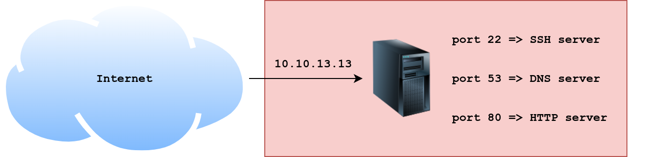
Consider the figure below. IP packets coming to the server with the IP address 10.10.13.13 will be delivered to the running process based on the destination port number.
- For packets of type TCP with port number 22, the destination process is the SSH server.
- For packets of type TCP with port number 80, the destination process is the HTTP server.
- For packets of type UDP (or TCP) with port number 53, the destination process is the DNS server.
We will not cover TCP and UDP in detail in this task. All you need to know for now is that these two protocols live on top of the IP protocol and connect processes running on different hosts. Moreover, TCP requires a three-way handshake for a connection to be established, while UDP does not.
References
This excerpt is taken from advent of cyber 3 tryhackme room day 10. All credit goes to tryhackme and the room/module author.
- day 10 of advent of cyber 3